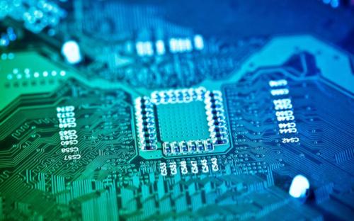
source:Other information release time:2023-03-17 Hits: Popular:PCB Assembly company

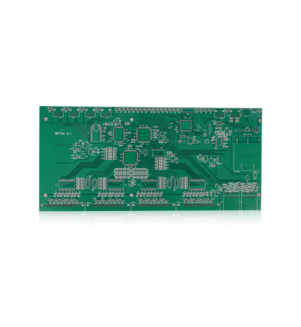
As a component of the whole machine, PCB generally cannot form an electronic product, and there must be problems with external connections. For example, between PCB, PCB, and boarding components, between PCB and device panels, electrical connections are needed. The use of reliability, craftsmanship and economic best coordination is one of the important contents of PCB design. Today, discuss the PCB plug -in connection method.
In more complicated instruments, plug -in connection methods are often used. This "building block" structure not only ensures the quality of product mass production, reduces the cost of the system, and provides convenience for debugging and maintenance. When the device fails, the maintenance personnel do not have to check the component level (that is, the cause of the failure caused by the check, trace the roots to the specific component. This work takes a considerable time), as long as it is judged which board is abnormal, it is as if it is abnormal. It can be replaced immediately, eliminating the fault in the shortest time, shortening the stop time, and increasing the utilization of the equipment. The replacement of the circuit board can be repaired within a plenty of time and is used as spare parts after repairing.
1. Standard pincture connection
This method can be used for PCB's external connection, especially in small instruments. Two PCBs are connected by standard pins. Two PCBs are generally parallel or vertical, which is easy to achieve mass production.
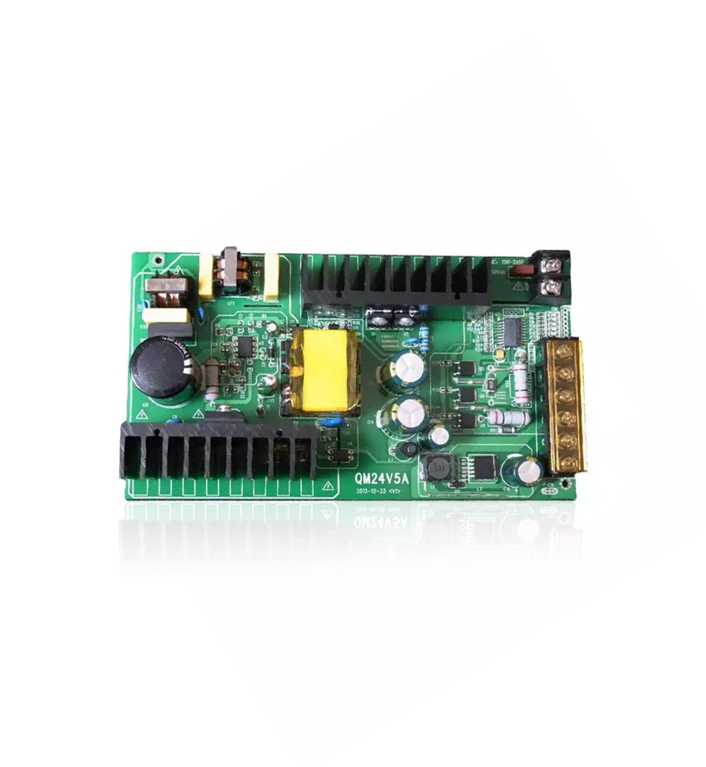
2. PCB socket
This method is made from the PCB edge. The plug part is designed according to the size of the socket, the number of contacts, the contact distance, the position of the positioning hole, etc., so that it is matched with the special PCB socket.
When making the board, the plug part is placed in gold, which improves wear resistance and reduce contact resistance. This method is simple, with good interchangeability and maintenance performance. It is suitable for standardized large -scale production. The disadvantage is that the PCB cost is improved, and the accuracy and process of PCB manufacturing are high; the reliability is slightly poor, and it is often inaccurate because the plug part is oxidized or aging of the socket reed. In order to improve the reliability of the external connection, the same lead is often led to the same or on both sides of the circuit board.
Read recommendations:
Welcome information, we will answer for you quickly

 No. 1 Jingtian Road, Xinsheng community, Longgang District, Shenzhen, Guangdong, China
 +86 13715096176
 Whatsapp/WeChat : +86 13715096176
 Kevin.kuang@xzgcircuits.com


 Return