source:Other information release time:2023-03-23 Hits: Popular:PCB Assembly company

The detailed drill type can be seen from the manufacturing steps. Special string symbols are placed on your PCB board, and the output description is added on it. Place the legend string symbol on the DrillDrawing layer.
Note: If the latest software version supports the detection of output processing files, it is best to detect your PCB processing file and check if there is a groove on your board. In addition, the earliest version commonly used methods include the description of the groove in the mechanical layer or welding layer, and the text description method is used. Some designers will place overlapping pads or over -holes to define the area where the drilling output is defined, but this may cause the drill bit to be destroyed.
When irregular holes manufacturing methods are different from the next board structure, you will find that your board structure is more suitable for processing. Therefore, there are three ways to define grooves.
Add detailed processing information to the mechanical layer to add multi -overlap pad or perforated application CAMTASTICNCDRILL features
Livedesignevaluationboard (eb1eb2) \ Spartan_Specific \ Spartaniibga4561.02EB1
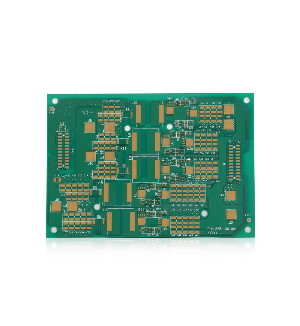
For details, you can find it in the mechanical layer Platedroutetails. Here you can see that the connection of the wiring is connected to the component J1, J6, and J2S. Converting to a single layer mode can see the initial settings of each layer (switch to the shortcut of a single layer mode: shift, s) wiring details are included in the component, so it will move the component when switching.
Before using this path, check the PCB processor to see if it is necessary to set a dog talent.
For this step, the area of pads and grooves must be built in the following sufficient support information to the processor:
Multi -layer pads with holes are set to 0 units. This is the default setting of the pads and cutting pads at the end of the groove. The size of the aperture for these pads should be the same as the size of the groove.
Place the thread on the mechanical layer of the plating channel details from the beginning of the start center to as dead as the pad.
You also need to carefully consider the inner plane connection of the groove pad, to reserve sufficient space for the inner plane to place the entity connection, and the thermal pads and empty pads need to be manually set. In this PCB example, the hot pads have been used -manually create arcs and lines, see the pads of J6 for details 1.
The connection rules for the plane connection set by the power supply pad can be directly connected. As for the design rules, check the setting of the power flat connection type setting rules directly connected to these grooves, (rules: Planeconnect_obround_pads, adding a category that has been set in the design of the design can be more easily set in the rules.) When the assembly is on the board, if you can't easily connect to the hot pad, you can choose a simple option to directly connect to these groove pads.
Finally, the groove pads cannot be connected to the plane. For example, the pad pads 2 and pads on the J6 need to apply copper on the cut -off area, so add a line or other objects as the flying wire to connect to the internal electrical layer in the shear area. Essence Because the plane is output negative.
Read recommendations:
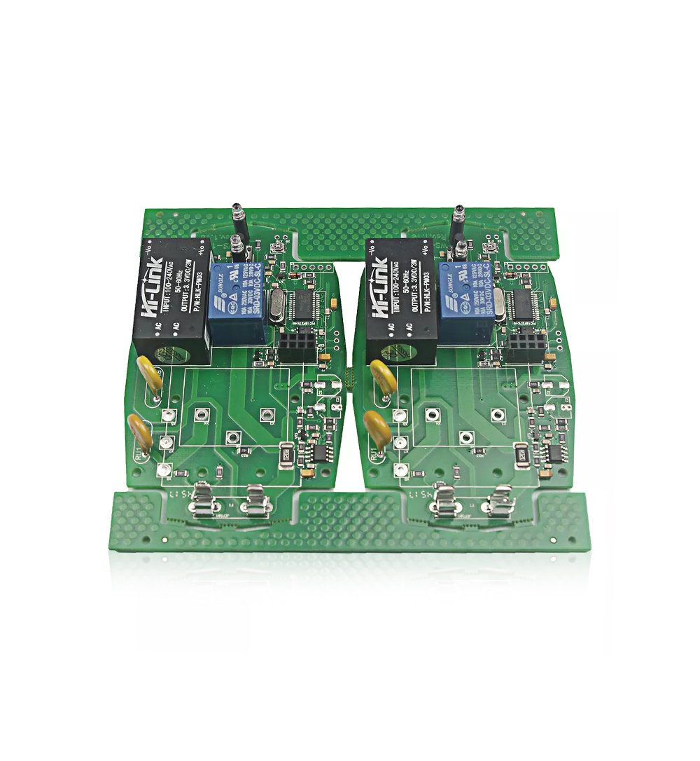
Blue Solder Mask Double Sided PCB Board High TG TG170 S1000-2
Welcome information, we will answer for you quickly

 No. 1 Jingtian Road, Xinsheng community, Longgang District, Shenzhen, Guangdong, China
 +86 13715096176
 Whatsapp/WeChat : +86 13715096176
 Kevin.kuang@xzgcircuits.com


 Return