source:Other information release time:2023-05-16 Hits: Popular:PCB Assembly company

When calculating the signal by changing the Fourier from the time domain to the frequency domain, the signal may contain several frequency components. The time domain signal is the sum of the frequency components that all contain, and the shape of the signal depends on the power level of each separate frequency. Digital signals contain a DC component, and then many low -intensity AC components, which increased with increased frequency. Fast signal means higher frequency components. Each of these communication frequencies is a very narrow frequency band, that is, a single -frequency sine wave signal. Therefore, digital signals are the sum of DC signals plus a large number of sine wave signals. The pure AC signal can be narrow belt (such as a pioneering wave) because they do not contain DC components.
Signal information is somewhere within the frequency range, and all the frequency components required by the information determine the bandwidth. The frequency outside the bandwidth is unnecessary and can be rejected, for example, by filtering, because these frequencies do not carry the additional information of the signal. Bandwidth can be considered as the working area of the telecommunications signal. In this area, it will not lose information, and it is also necessary for the circuit (that is, the wiring) or load of the signal. Then design the electronic equipment accordingly, and in the best case, when the signal is fed in the wiring, it remains unchanged. If the signal speed is higher than the bandwidth of the wiring or filter, the signal will be modified, which usually means that some frequency components will be filtered out. The tracking itself will have bandwidth limit,
The bandwidth of the signal is required by the signal increase time (10%to 90%). It can be represented by the following experience:
Bandwidth = 0.35 / TR (1)
The signal frequency is not as important as the rising time requirement, just because the signal is different. Even if the signal frequency is exactly the same, the requirements of the digital signal (the duty ratio of 50%) and the PWM signal (the duty ratio of 10%to 90%) are different. In the PWM signal, when the signal "open" status is short (90%) (90%) (90%) (the duty ratio is 10%), this means that compared with the longer "opening" state pulse, the rise time must be faster. It's much more. Of course, the frequency of signal is also very important, because the higher the frequency, the faster the rise time. This rules of bandwidth experience are the first tool I used for signal bandwidth -related design tasks. I learned from the electronic design lecturer of my university a long time ago. Since then, I have used it many times in the design.
Read recommendations:
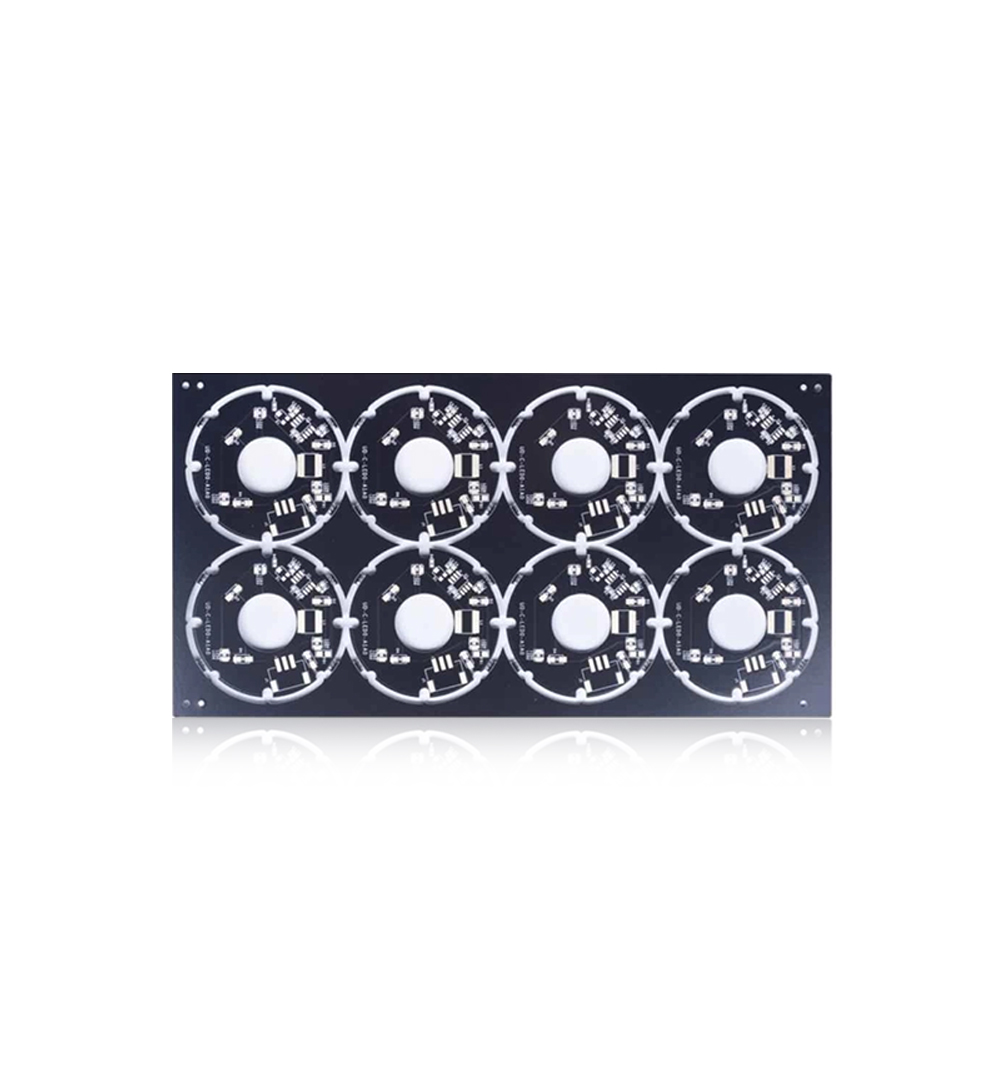
Lightweight Aluminum PCB Board Green Solder Mask Led Light Pcb Board 3.0mm
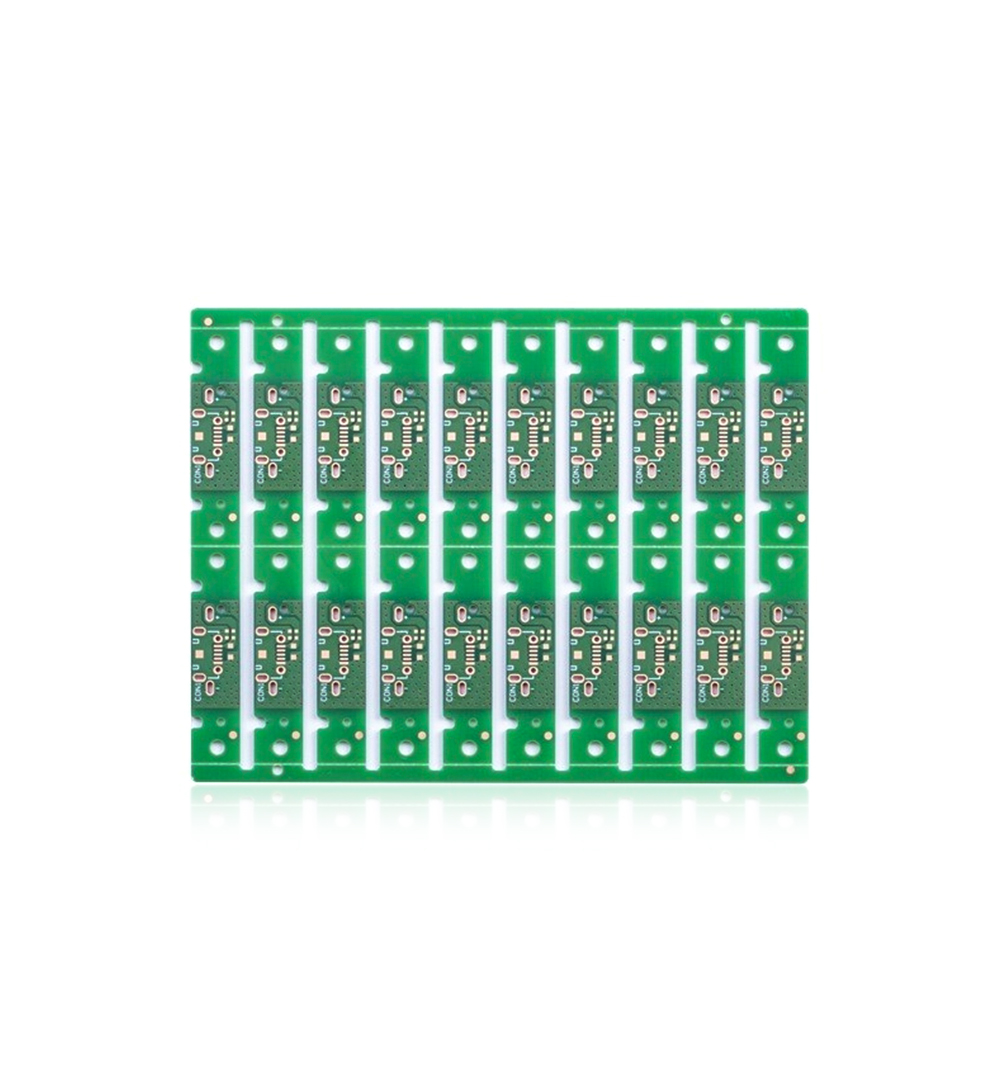
Polymer Film Flex PCB Board 0.1mm 2 Layer Rigid Flex Pcb Lightweight
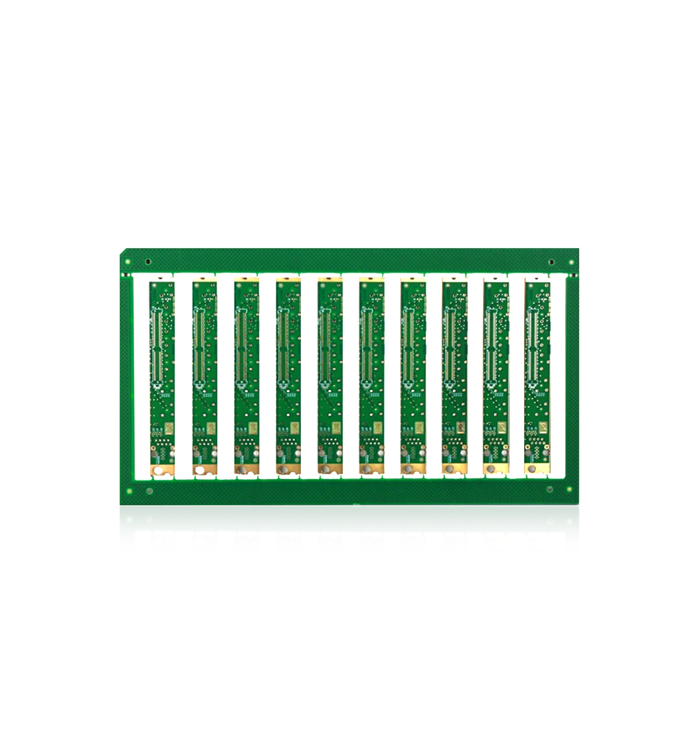
Multilayer Printed Circuit Board 1OZ 4 Layer Multilayer Pcb FR4 TG170 Blue Solder Mask
Welcome information, we will answer for you quickly

 No. 1 Jingtian Road, Xinsheng community, Longgang District, Shenzhen, Guangdong, China
 +86 13715096176
 Whatsapp/WeChat : +86 13715096176
 Kevin.kuang@xzgcircuits.com


 Return