source:News release time:2023-09-14 Hits: Popular:PCB Assembly company

1. Definition of high-speed circuits
Usually, if the frequency of a circuit reaches or exceeds 50MHz, and the circuit operating above this frequency accounts for more than one-third of the entire system, it can be called a high-speed circuit. In fact, compared to the frequency of the signal itself, the harmonic frequency of the signal edge is higher, and the rapid change of the signal's jump (rising or falling edge) leads to unexpected results in signal transmission. The transmission of a signal occurs at the moment when the signal state changes, such as the rise or fall time. If the signal passes through a fixed period of time from the driving end to the receiving end, and the line propagation delay is greater than half of the rise time of the digital signal driving end, it can be considered as a high-speed signal and generate a transmission line effect. If the transmission time is less than half of the rise or fall time, the reflected signal from the receiving end will reach the driving end before the signal changes state. Otherwise, the reflected signal will reach the driving end after the signal changes state. If the reflected signal is strong, the superimposed waveform may change the logical state.
2. Determination of high-speed signals
In PCB design, the actual wiring length determines the propagation time of the signal. If there are too many vias, too many component pins, or too many constraints set on the network, it will lead to an increase in latency. In general, the signal rise time of high-speed logic devices is about 0.2ns. T represents the signal rise time, and Tpd represents the signal line propagation delay. If Tr>4Tpd, the signal falls in a safe area; If 2Tpd
Read recommendations:
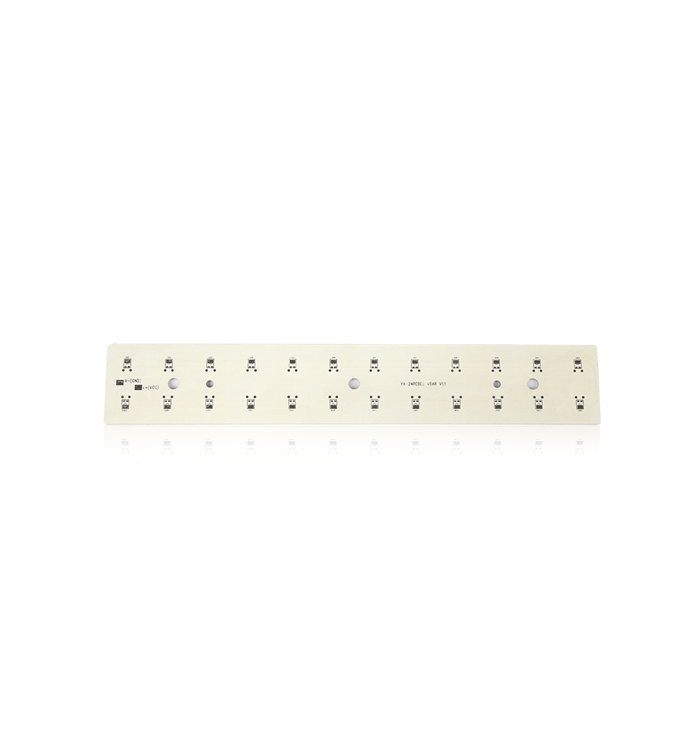
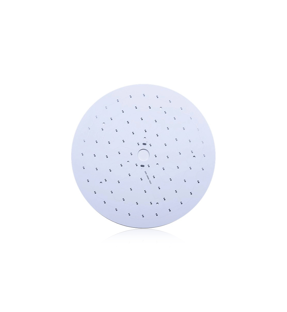
Metal Core 0.8mm Led Street Light Pcb Aluminium Pcb Board For Led
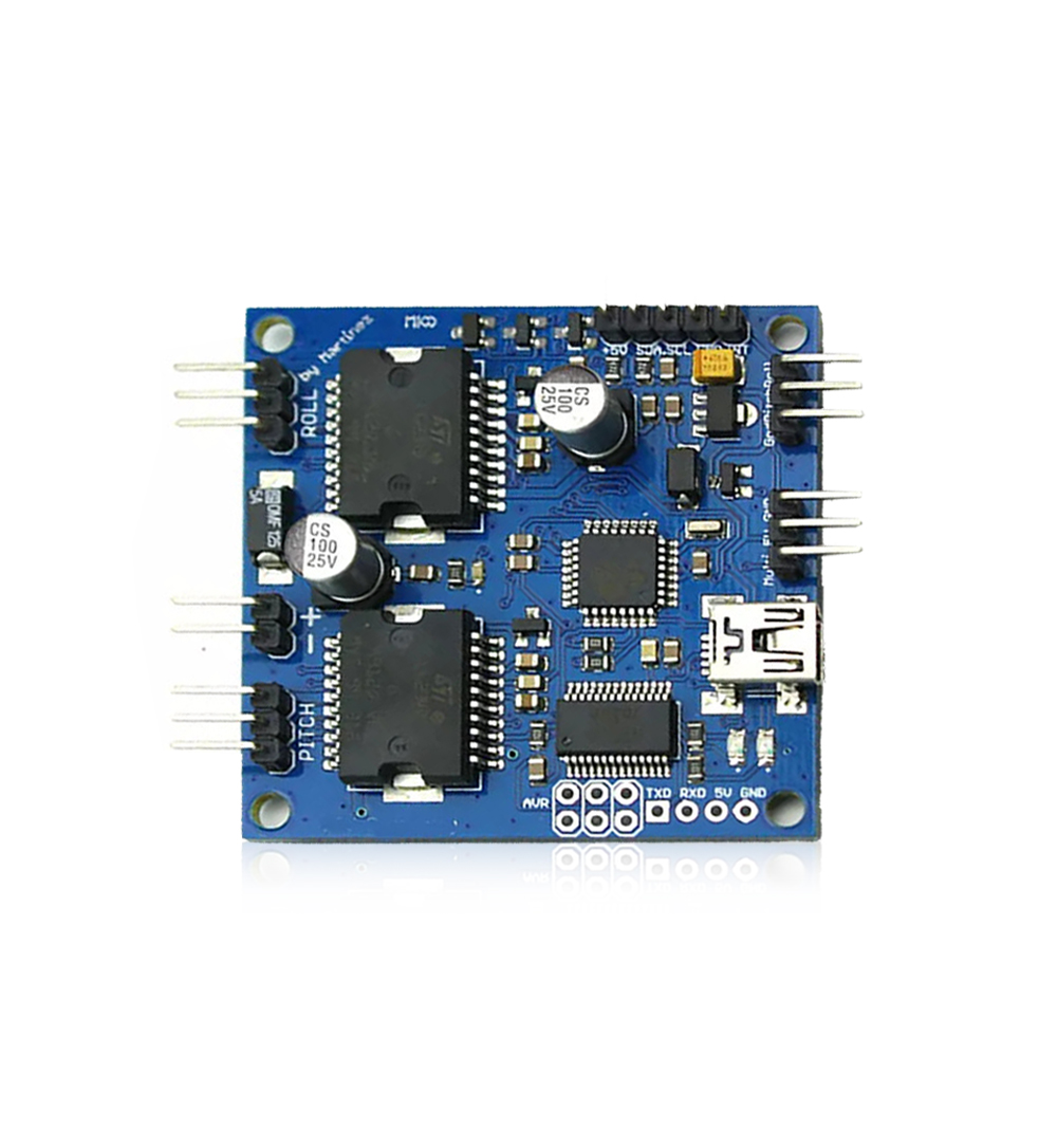
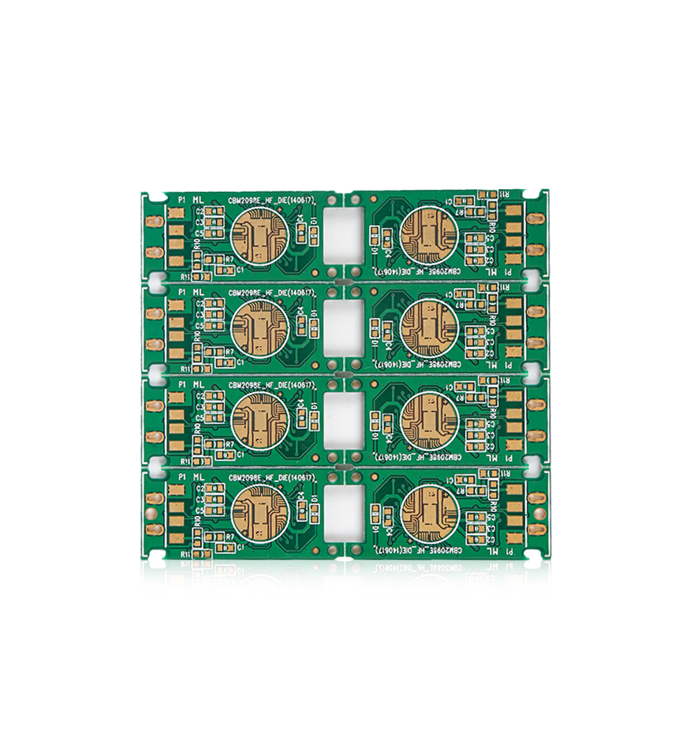
Green Solder Mask FR4 Single Sided PCB Board 0.4mm Halogen Free
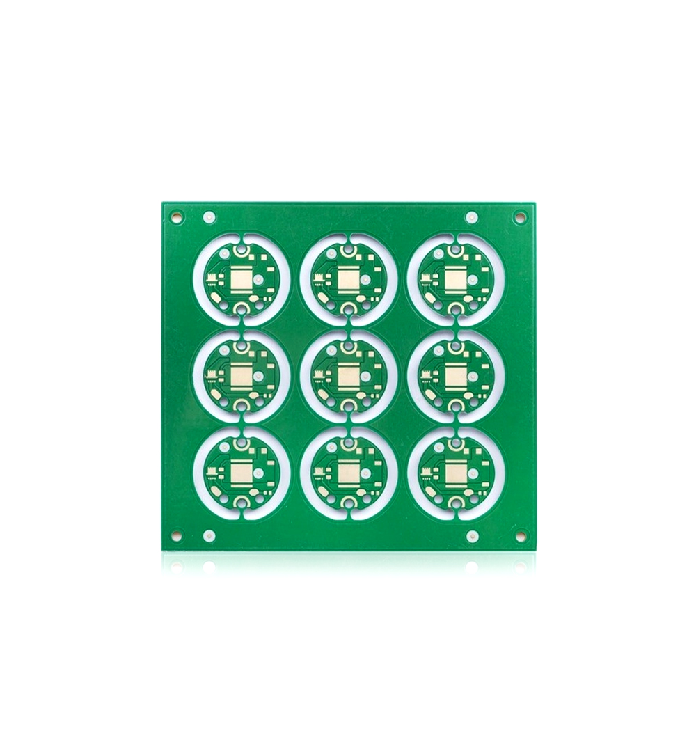
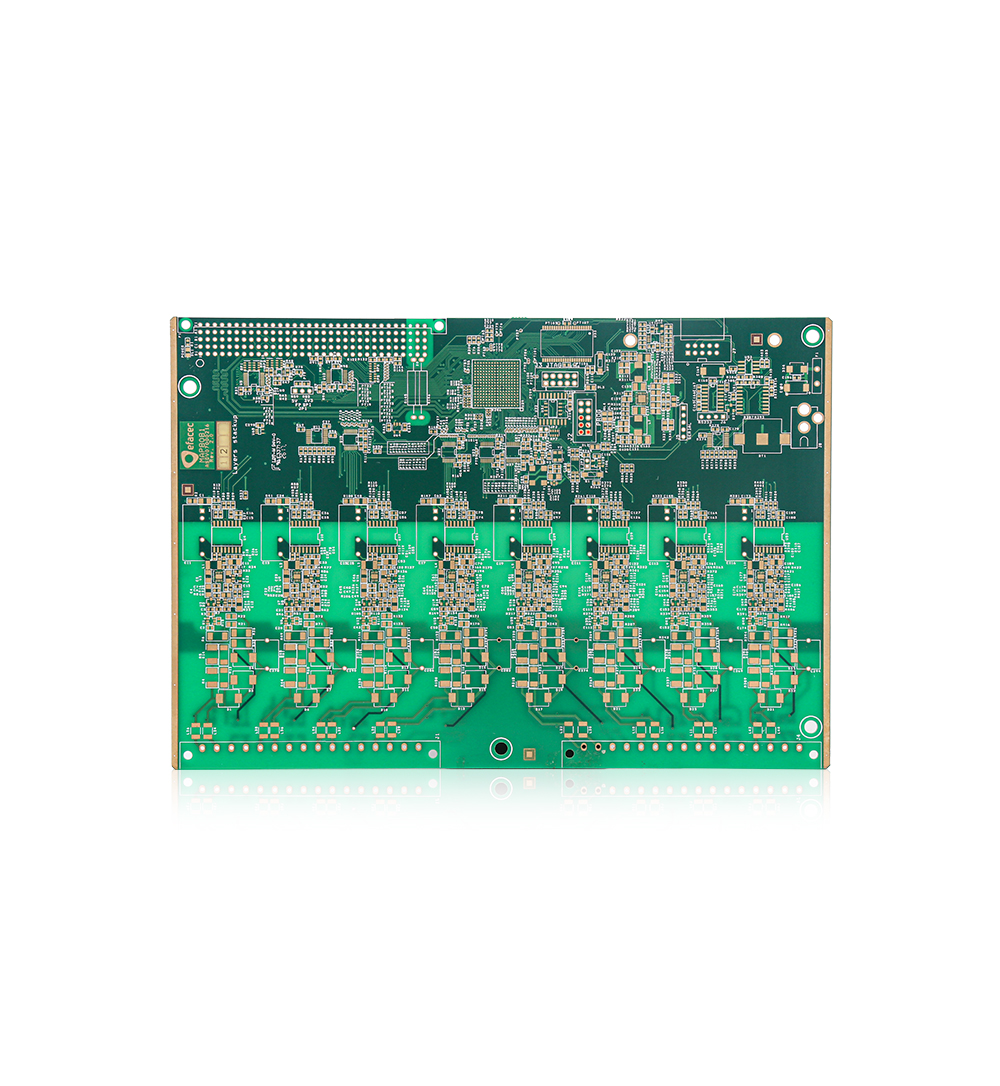
FR4 TG170 Rigid Flex PCB Fabrication Immersion Gold Green Color Solder Mask
Welcome information, we will answer for you quickly

 No. 1 Jingtian Road, Xinsheng community, Longgang District, Shenzhen, Guangdong, China
 +86 13715096176
 Whatsapp/WeChat : +86 13715096176
 Kevin.kuang@xzgcircuits.com


 Return