source:Other information release time:2023-06-02 Hits: Popular:PCB Assembly company

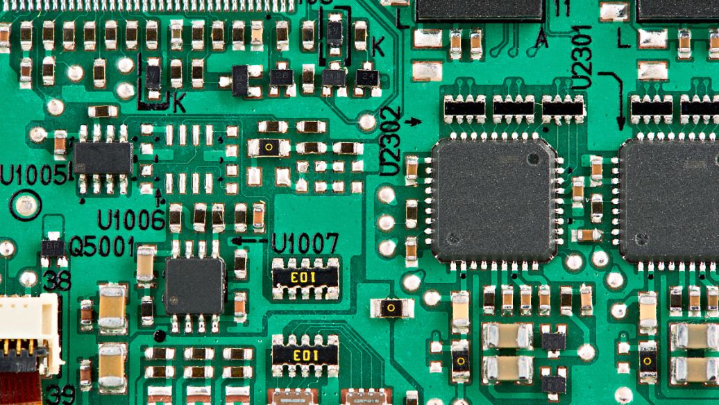
With the switch of the SWITCH, the current in the inductance L also fluctuates up and down at the valid value of the output current. Therefore, there will also be a ripple that is the same frequency as Switch at the output end. Generally, the ripples that are said to refer to this. It is related to the capacity of the output capacitor and ESR. The frequency of this ripple is the same as the switching power supply, which is tens to hundreds of kHz.
In addition, Switch generally uses bipolar transistors or MOSFETs. No matter which one is, there will be a rise and decrease time when it is turned on and dead. At this time, there will be no noise in the circuit that is the same as the increase time as the Switch rising decrease time, or a few times, and is generally tens of MHz. Similarly, the diode D is in reverse recovery. The equivalent circuit is the series of resistance capacitors and inductors, which will cause resonance, and the noise frequency is tens of MHz. These two noise are generally called high -frequency noise, and the amplitude is usually much larger than the ripple.
If it is an AC / DC converter, in addition to the above two ripples (noise), there is also AC noise. The frequency is the frequency of input AC power supply, about 50-60Hz. There is also a co -mode noise, because the power device of many switching power supply uses the shell as a radiator, which produces an equivalent capacitance.
Measurement of switching power ripples
Basic requirements: Use the oscilloscope AC coupling, 20MHz bandwidth limit, unplug the probe ground
1. AC coupling is a superposition DC voltage to obtain accurate waveforms.
2. Opening the 20MHz bandwidth limit is to prevent interference of high -frequency noise and prevent the error result. Because the amplitude of high -frequency composition is large, it should be removed when measured.
3. Unplug the ground clip of the oscilloscope probe, and use the ground measurement measurement to reduce interference. Many departments do not have ground rings. But consider this factor when judging whether it is qualified.
Use a 50Ω terminal. According to the information of the Henghe oscilloscope, the 50Ω module is to remove the DC component and accurately measure the AC component. However, there are few oscilloscopes with such special probes. In most cases, the use of probes from 100kΩ to 10MΩ is used, which is temporarily unclear.
Read recommendations:
Impedance Control Double Side Prototype PCB 4mil FR4 TG150 Matt Black
Welcome information, we will answer for you quickly

 No. 1 Jingtian Road, Xinsheng community, Longgang District, Shenzhen, Guangdong, China
 +86 13715096176
 Whatsapp/WeChat : +86 13715096176
 Kevin.kuang@xzgcircuits.com


 Return